|
Intercooling is an area of particular interest to me, and I have spent years developing a set of guidelines that pertain specifically to Air-to-Water (A2W) intercooling. These principles of optimization
apply to any car, and I have been consulted on many forums, but the mid-engine layout of the MR2 makes it a particularly good candidate for A2W intercooling since cold airflow to the oem A2A intercooler is poor. I have also posted this on the MR2 Owners Club forum. I am not selling a particular product. Let's get to it.
LEGEND for the Ultimate A2W Tips and Tricks Guide
The Ultimate A2W Tips and Tricks Guide INTRODUCTION
In order to arrive at a definitive A2W guide, we must use an example of a car subjected to the most gruelling intake air temperature (IAT) challenges; a top-speed record perhaps, or a prolonged road-race (several hours). The principles and real-life components of a successful build in such environments serve to guide us in our designs... let's call them optimization principles. In such a hostile environment, the A2W system must have excellent recovery so that the IAT's plateau at a safe level, and can do so all day long.
So what exactly is recovery? In loose terms it is the opposite of "heatsoak". Water is far better at absorbing heat than air is; it has a much larger heat-absorbing capacity. But this capacity is meaningless without the ability to transfer heat out of the water at the HE, and heat into the water inside the IC. Without this ability, all you are doing is storing heat in a heavy "bank" of water, which takes increasingly longer to recover. Maximizing heat exchange in these two crucial components is the single most important factor in an A2W system, and this determines recovery.
To achieve this, each of those components should be as large as can be fitted in the design, and as good a quality as can be within budget. Beyond this, the most crucial factor for maximum heat exchange is going to be flow, flow, flow. Flow and the ensuing recovery eliminates the need for a large amount of water volume. I will address the specific application of a larger reservoir later.
To explain the importance of flow, let's immediately address a big misconcetion of A2W intercooling regarding the rate of water flow in the system. The scientific fact is, flow is everything. The more flow, the better, all things being equal. The MYTH is, "the speed of the water needs to be juuuust right to allow time for the heat exchange to take place... too fast is bad." An erronious statement! The greater the rate that water is flowing through both your heat-exchanger (HE) and intercooler (IC), the better the:
- temperature differential at both components, which translates into faster exchange
- turbulence inside your components, since laminar flow exposes fewer molecules for exchange
- circuit-time for the water, getting heat out faster and cold in faster
- amount of "working" water in the system, as opposed to eddying around in some oversize reservoir
The biggest contributers to maximizing flow are all dependent on each other, and they are:
a) Good pump as described below. Names/brands/types will vary, look at the stats.
b) Diameter of the fittings/lines/inlets/outlets of all components throughout the system
c) The total amount of bends in the system, and the sharpness of the bends. Minimize both of these.
d) Pressure-drop in the water-side of the IC and HE, water endtanks, and positioning of the inlets/outlets
If your system is great at all of the above, there is no need for a huge amount of water in the system. I have thoroughly tested and proven this. In my 2.4-gallon reservoir-less system, recovery takes about 30 seconds, and it can do this all day long.
When building an A2W system, we need to derive (first and foremost) what its design limitations are (the budget for materials, budget for time, modification/cutting of car body, the car's application for street, drag, track/course, total power goal, and aesthetics). These limitations determine how we choose, apply, bend, and sometimes even forego a few of the optimization principles. Let's move on to ten distinct sections which help achieve our A2W build:
1) PUMPS - learn what pump flow ratings mean. There is so much misleading advertising with regards to flow.
A pump flow rating is meaningless without a specific pressure indicator. So, look at the fine print or flow charts, and it will show you that the flow rating drops as the pressure increases. What you need is to be able to compare pumps at the same pressure. For example, 21 GPM@3.6psi.
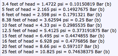
- For our A2W systems look for a pump that is capable of putting out 10 - 15 GPM @ around 5 PSI. Since pressure ratings can be in bar, psi, or feet-of-head, here is a conversion chart:
- When a pump is advertised as a 1500 GPH pump, it is usually an "open-flow" rating, which means @zero pressure. As pressure increases a few psi, the flow-rate can decrease dramatically. Rule pumps are a good example.
Look at what the pump puts out at above 5 psi. If you cannot find any stats on what a pump puts out above zero psi, avoid it. Rule pumps are generally bilge-pumps, not intended for pressure. Our A2W systems are circulation, often with 3/4" lines, likely having pressure somewhere in the 5 - 8 psi range, depending on your pump output and overall pressure-drop. I am not coming down on Rule specifically, but they have misleading stats and I see them often used in pressure situations that they are not intended for.
- Generally, price is also a decent indicator. It is unlikely to get the performance we want for under $100. Sorry.
- Pumps should always be connected to lines/fittings that are equal to or larger than the pump inlet/outlets. Don't think of connecting a Rule pump (or any pump for that matter) with a 1" or 1.25" or 1.5" outlet, to 3/4" lines.
- Get a circulation pump, intended for continuous use. This is especially important if you wire the pump to run continuously with ignition on... lol. The exception to this is drag-strip or track-only car, where the pump won't be on for very long anyway. Otherwise, you might have to replace your pump sooner than you would like.
- Place the pump as low in the system as possible. This will help with priming and operation. Pumps like to push... they hate to suck.
- Pumps do not like to dry-run. Be aware of running a pump for a long time if it is not primed and therefore not pumping water.
- Regarding voltage, make sure you are buying a 12-volt model! Especially on ebay, you may find your new bargain is actually a 24-volt model. Also be aware that performance will vary somewhat depending on alternator output.
- Here are current available pumps with links, stats, and prices, in random order, that range from "getting the job done", to really "maxing out the flow". At the bottom I ranked them according to numerous available stats, cost, and suitability. I've also included a few not-so-suitable, for comparison, and to demonstrate why.
Pump stats and parts change from year to year, even the company names, so please check stats and model numbers. Pumps are often discontinued or replaced with newer lines, but this is as of 2010 and 2011 catalogues. Prices will vary, so hunt around!
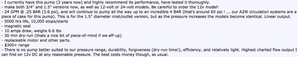
Johnson CM90
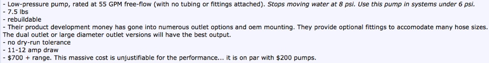
Jabsco High-pressure pump
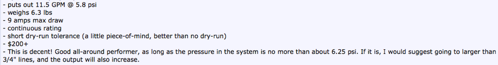
Jabsco Low-pressure pumps (50830, 50840)
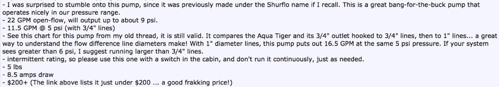
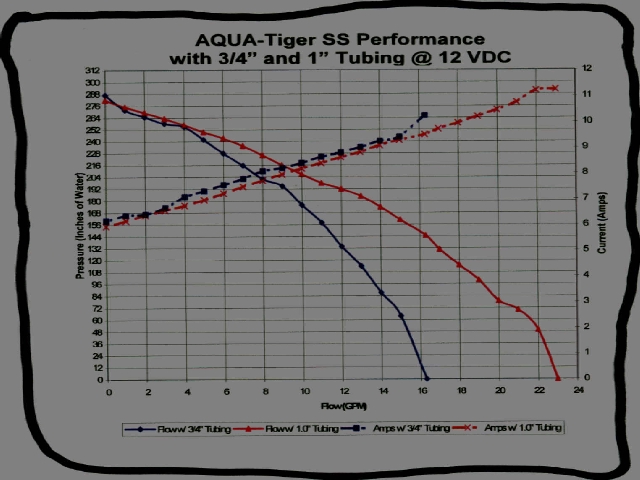
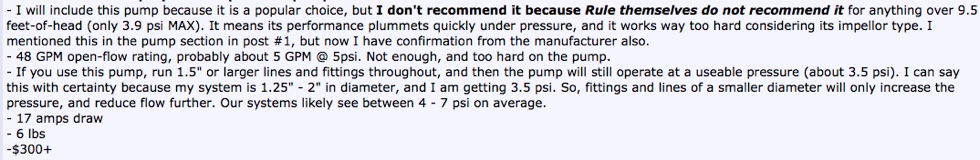
Sherwood Aqua Tiger
Meziere WP 3xx, or "55GPM" line remote electric pumps
Meziere WP 136S/137 "20 GPM" line remote electric pumps
Rule 3800 / 3700 General-purpose low-pressure bilge pump
- I want to point out that Rule has designed these bilge pumps for low pressure, and specifically equip them with 1.5" inlets/outlets for the reason that they are not designed for pressure. Their 4000 GPH model comes with 2" inlets/outlets, and their 8000 (twin 4000) model comes with a 3" inlet/outlet. You must use line diameters/fittings equal to or larger than the pump's inlets/outlets.
Bosch "Lightning" pump (part 0 392 022 002)
In summary, here are my pump ratings:
Rank #1: Johnson CM90 - Best performer and features, price is reasonable considering the product.
Rank #2: Jabsco Low-pressure - Best bang-for-the-buck. I rank it above the Aqua-Tiger only because it has a continuous rating. Only downside: does not perform so well when above 6 psi with 3/4" lines.
Rank #3: Sherwood Aqua Tiger - Best bang-for-the-buck. Overall good performer, well-suited for us. Only downsides: intermittent rating, and prefers larger than 3/4" lines if the system pressure is over 6 psi.
So there you have it! For example, At 5 psi on 3/4" lines, the Aqua Tiger or Jabsco will spank the Rule 3800, Meziere WP136S "20 GPM", and the Bosch. Spank! The Aqua Tiger or Jabsco should be the cost-effective go-to pumps for most MR2 A2W applications.
But if you want the king, go Johnson CM90.
2) FITTINGS / HOSES / LINES / INLETS / OUTLETS
- Make all of these as large as you can. The larger, the better. Flow is everything. Why? Because turbulent flow provides the best heat exchange, replaces the heat-absorbed water faster, reduces your overall system temperature, and gives you the fastest recovery.
- Running larger than 3/4" lines is quite possible, but more difficult for fitment. 3/4" will get the job done, I would set this as a minimum requirement. I run 1.25" - 2" throughout the entire water-side.
- Minimize any sharp bends. Every bend adds to your pressure-drop, the system pressure that your pump will have to overcome. If you must have a 90-degree bend, make it as gentle as possible.
- Run the lines away from heat sources, if you can. If you use hardlines, be aware that you want some flex at the couplings.
- Understand the relationship between line/fitting diameter + bends combined with pump output. Ultimately we want the highest flow at the least pressure. The better the pump, the higher the pressure it is capable of. Our A2W circulation systems typically see between 5 - 8 psi, depending on the pump output coupled with the line/fitting diameters + bends. A fantastic pump running through 3/4" lines can be out-flowed by a medium-output pump running through 1.25" lines at lower pressure.
The best flow result is a fantastic pump combined with large lines and few bends... high flow at lower pressure. Currently I get up to 27 GPM, at 3.0 - 3.5 psi, running a Johnson CM90 through 1.25" - 2.0" lines. The great Johnson CM90 running through 3/4" lines may see as much as 8 psi, which reduces it's flow to around only 5 GPM. All other pumps listed will flow even less. This is why I recommend what I recommend.
3) HEAT-EXCHANGER (HE)
- The best location is in the front of the car, in front of the radiator, because it provides unlimited ambient air to the exchanger, and is exposed to the least heat sources.
- Place it away from the radiator, not touching it, in a "v" shape if you can. Those also running air-conditioning exchangers will find space quite limited and will likely have to place all three components against each other. This is ok because the air-con rad will act as a buffer. Still place the A2W exchanger in front.
- Get the largest HE you can fit. I opted for a shorter very thick Fluidyne, intended for the Mustang Cobra, but thinner larger surface-area exchangers will work well. Even the oem Mustang Cobra HE's (2003 and newer) work well, and can be found for very cheap used.
- The inlets/outlets should be 3/4" minimum as noted above. Close off smaller inlets/outlets, and have larger appropriate inlets/outlets welded/brazed back on, in the locations best suited for your install... but remember that it is best to have the water go through as much of the HE core as possible, so place the inlets/outlets kitty-corner to each other in a singe-pass HE.
4) INTERCOOLER CORE (IC)
- Run the largest IC core you can fit. The greater the surface area for exchange inside, the better. There are many types, some will exchange better than others, but even Ebay cores will work.
- Locate the IC in the coolest location possible. If you don't mind sacrificing trunk space, this is a good location at the expense of longer air-pipes. I located mine upright in the bottom left corner of the engine bay, down in front of the tranny. This is the coldest part of the engine bay. Get the IC as far from the turbo/exhaust manifold area as possible.
- If your IC has smaller than 3/4" inlets/outlets, remove them, and weld/braze new larger inlets/outlets in locations to suit your install.
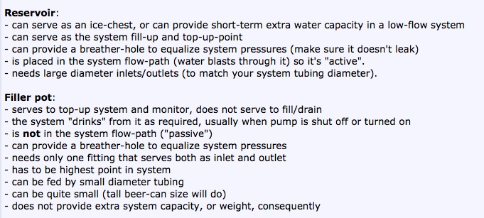
5) RESERVOIR
- The best use for a reservoir is to be able to fill it with ice. Having a large inline reservoir with large water capacity is not necessary in a system that is well set-up with good overall water-flow, unless you specifically want to run ice for the drag-strip. Falling back on a large reservoir to shoulder the heat-absorption of a low-flow system is a band-aid. It will buy you time due to capacity, but it will take the low-flow system much longer to shed the built-up heat.
- An ice-chest can be made removable using quick-disconnects and valves, so that just for drag racing the reservoir filled with ice water is swapped in. The water then only circulates to the ice-reservoir in the trunk, by-passing the HE. This will maximize the cooling potential of the ice for the short-duration drag runs. A drag-only car can also be built without a HE, relying just on ice.
- Place it in the coolest location possible, like the trunk. Subjecting the reservoir to engine-bay heat only adds to the heat that the system has to overcome, and will melt ice faster.
- The reservoir cap/opening should be the highest point in the system, to aid with filling up. That is where the bubbles will eventually go, and you can keep topping up while you run your pump until you get all the bubbles out.
- I run reservoir-less, and thanks to my flow, I'll never need one.
- Some heat-expansion pressure or vacuum can build up in a sealed system. I use a small filler pot to balance this pressure fluctuation, and it serves as my top-up and monitor point. Here is an explanation of how I define the difference between, and the uses for, a reservoir vs a filler pot:
6) CIRCULATION FLUID
- Distilled water is best. To help with corrosion, a bottle of water-wetter in the distilled water will do the trick. When filling up the system, I would get all the bubbles out of the system, and then add the water-wetter last. Water wetter itself creates small bubbles, so expect to see a foamy look. These bubbles affect the water's surface tension.
- For freezing winters, swap out some of the distilled water for anti-freeze, as appropriate for your local temperatures. Anti-freeze also helps fight corrosion, but won't give you as good of heat-exchange as distilled water.
7) PLANNING, ROUTING AND INSTALL
- Plan, plan, plan! Draw it all out first. Line things up. Research your components. It won't be a quick job, if done right, but it will be worth it.
- Prioritize! Decide if you want to compromise trunk space, etc, and how much you are willing to cut. 3/4" lines are convenient because you have various line choices in both flexible and hardline forms, and cutting can be avoided, but larger lines will yield better flow volume at less pressure. I decided I would only compromise some front trunk ("frunk" or bonnet) space, and was willing to cut to accommodate 1.25" - 2" lines.
- Depending on your priorities, the routing will likely change or vary a fair bit. Here are some things to keep in mind for routing:
. 1) Decide on a high point in the system from which you will do all the filling.
. 2) Try and place your pump at or equal to the lowest point (often a large section of tubing might all be at the lowest point, this is fine).
. 3) It also helps to have a way of draining or pumping out all of your liquid... it helps to have this near the low point as well.
. 4) It has been shown that turbulence is a key factor of good exchange within the two exchange components, and that placing a pump reasonably close preceding a component will create the most turbulence inside... Since I have high flow/turbulence already at 27 GPM, it was not a priority for me.
. 5) If running ice, I would place the ice chest/reservoir right before the IC, so that the cooling potential of the ice's change-of-state is maximized. It will be beneficial to temporarily bypass the rest of the system (HE and piping) and have a short loop between the ice chest and the IC core only. This would apply mostly to 1/4-mile drag, since ice lasts maybe a minute, and the water will heat up quickly with no cooling mechanism.
. 6) The theory of counter-current exchange can play an important part in exchange efficiency inside the IC core. Important to note: This only applies to dual-pass IC's and barrel-type IC's. For single-pass "regular" a2w cores, the direction of water-flow does not matter. But for dual-pass or barrel-type A2W cores, you want the the cold water from the cool side of the HE to go into the cold side (throttle body side) of the IC core, and the hot water exiting the core should come out of the hot side (turbo side) of the IC.
. 7) My routing is: HE>pump>IC>(back to)HE, but routing is not crucial unless you have an ice reservoir.
Other things to keep in mind for installation:
- Make good solid mounts for your components. To reduce pump noise, wrap the pump in some larger diameter hose, and clamp it with good hose-clamps. Rubber bushings where the pump-mounts bolt to the car will also reduce noise transfer. This will help, and be an advantage over the usual mounts that come with pumps. With regards to holding your lines in place under the car, there are various methods that work, but I have found that, surprisingly, heavy-duty zip-ties are cheap, very tough, take up no room, are easy to install, and don't rust or corrode.
They have held my 1.25" copper and pvc hardlines in place for five years now. Obviously, don't use them next to a massive source of heat like the turbo or exhaust.
- Pump wiring is subjective, but I like to have my pump on a switch that I can control manually. This is helpful when filling up the system and getting the bubbles out, etc, without having to run the engine. It is also not necessary to run your pump for several hours of highway commuting, especially off-boost. A switch in-cabin lets you turn it on only when you really need it. With the pump off, your IC temp will climb, but won't hurt anything as long as you aren't driving hard.
- Temperature display is also very useful, to monitor results of your install, and serve as a warning if your system has failed and the temperature is climbing, or, your pump might be dry-running if the fluid has leaked out, etc. There are various ways to accomplish this. I see temp recovery in under 30 seconds.
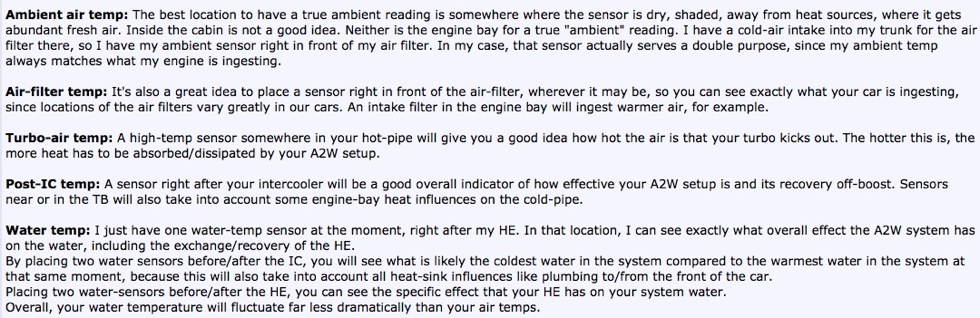
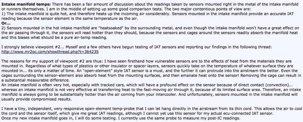
8) TEMPERATURE SENSORS and LOCATIONS
We may not need all of the following sensors, but having sensor readings to ensure our A2W system is functioning properly is an excellent idea. Here are some explanations and my recommendations:
Another note regarding locations and sensor housings is still being tested, but I have seen enough evidence to post it here:
Here are some links for temperature probes, displays, and responsive IAT sensors that work well:
- These are expensive, but very functional:
SPA Digital Intercooler In/Out
- This one can be modified easily to work, but provides other information like compass and time as well, if you can handle the display... it's what I use for portable/moveable independent IAT readings. I also now use the sensor alone with my micro-controller setup:
RoadPro In/Out temperature Display with External Probe
- Here is how to make your own:
DIY Temperature Sensor Display
- For just a responsive IAT sensor alone (no display), which will connect directly with the factory Toyota 3sgte ecu to report IAT's, see this review of the RIAT:
RIAT IAT Sensor
9) SPECIFIC APPLICATIONS
The inherent principles of optimization outlined above will serve well in all scenarios. Lets perhaps look at more specific application which warrant some extra considerations:
THE DRAG RACE
Believe it or not, I see some of the worst A2W designs in drag applications, because people can get away with it since drag races are so short. For example, you could literally spew out all of the water coming from your IC onto the track as long as it takes your pump longer than the lenghth of your elapsed time to empty your system.
It's why so many high horsepower cars claim "my 1/2-inch A2W water lines are just fine for my massive power, it's what works best for me, it's all you ever need, why bother with anything more?" and then they use their dyno horsepower number to justify their A2W build (just ask them what their IAT's were on their 20th dyno pull of the day). Yet if they put that car in a 30-minute race, the IAT's will climb into the stratosphere, and their big reservoir full of hot water will keep that toasty temperature up there for an hour of recovery time. So to start, let's optimize the drag-only setup, reducing weight, leaving out the HE altogether, and truly keep IAT's as low as possible for that short time period.
The primary cooling comes from an ice chest, or large reservoir designed to be filled with ice. Here are the:
Advantages
- less weight possibly, since there is substantially less plumbing (none to the front of the car) and no HE component.
- less cost
- easier install
- can have colder than ambient IA temps for short periods
- since the trunk is the best location for an ice chest, we can run very large lines because there is room to do so.
- very short water tubing will allow the water to make a complete circuit in a shorter time period, providing more cooling/heat exchange for a short period, until the ice is gone.
Disadvantages (some of this is rhetorical or obvious, sorry)
- drag-only, no proper cooling for street or road-course boosting
- the hassle of ice, constant draining and filling
- I recommend large lines, so large holes in the trunk firewall
So, lets talk a few details of components and install. To present what I would consider optimal, here are two methods that will work:
Drag Setup A
Reservoir
- good sized reservoir (ice chest). This is a bit open for individual build requirements and power, but I would say two to three gallons. Filling it with fresh ice after every run works best. You want to have some ice left in the reservoir after each run because this means you have optimal cooling through your run. A smaller reservoir might do depending on your power/heat level. If all your ice is gone after one run, perhaps consider a larger reservoir.
- large wide filler lid will make it easier and faster to fill. Consider a small air-pressure vent tube to extend up out of the lid to allow pressure-equalization of expanding/contracting water and air inside, but no spilling. The reservoir has to be the highest point in the system (besides the vent tube end).
- drain-valve out the bottom of the reservoir, with a tube running out of the car, to drain off excess fluid from melted ice
- inlet (warmer water from IC) should be high in the reservoir, with the top of the inlet level with the surface of the water/ice. This will send the warmer water spurting straight into the floating ice.
- outlet at the opposite and bottom corner. This will keep ice from entering. Perhaps a non-restrictive grate to ensure this
- put the reservoir in the trunk. Its the most logical place, easiest to fill with ice there, the coolest too
Piping
- as few bends in the water tubing as possible! It should be 100% possible to design those pipes so that the water in completing one "lap" turns a total of 360 degrees, including the changes of direction in the IC and reservoir. For potential designs, examine the routing exhibited by several fine examples of trunk-mount A2A tubing... this will give you ideas.
- this can be done for fairly cheap using 1.5" or larger abs or pvc, or even 2" vacuum pvc (its the lightest, thinner walls). I use some of this 2" vacuum pvc in my tighter bends. Aluminum/copper lines in this diameter are expensive, and would require hose couplings for flex. Can also be done all with hose... but pick some decent stuff since the cheap stuff can crack
Pump
- with large lines at least 1.5" diameter, make sure you get a pump with at least 1.5" inlets and outlets!
- it is perfectly fine in this instance to use the Rule 3700 or 3800 model bilge pumps. I would guess that the total pressure drop would be in the 2.5 psi neighbourhood... so this is now nicely in the efficiency range of those Rule pumps! They should be putting out over 30 GPM at that pressure level, drawing about 12 - 15 amps.
- for comparison, the Johnson CM90 will also be putting out over 30 GPM, but doing it a bit more efficiently at 10 amps.
- the big Meziere pumps (WP 3xx line) are also suitable here. Make sure to select the big 1.5" inlet/outlet options when you buy this pump. Expensive though. The smaller WP 1xx line pumps do not have as good an output, and will be eclipsed by the large Rule and Johnson CM90 pumps, for the same money.
- you can get away with using a non-continuously rated pump... just remember to shut it off
- as usual, place the pump the lowest in the system
Intercooler
- Go for it. Get a dual-core. Get the largest you can. Get the largest you can fit.
- for best location, I say the trunk. You should be able to fit a massive IC in one side of the trunk, and the ice chest in the other side. This means more tubing and more cutting holes in the trunk firewall, and longer IC piping... but its the only place you can fit those really big chunky IC's that are rated for like 5000 HP, lol
- or, mount a big dual-core unit in the "usual" location on the left side of the engine bay. Keep the IC away from heat as much as possible. Don't put it over the exhaust manifold or on the engine. This is the easiest install, and the shortest IC piping
- or, consider having a custom IC made, to pick your cores, optimize your endtanks for the install and better airflow! Plus you get to put your water inlets outlets where you want also.
- Remember the theory of counter-current exchange for dual-core IC's, and route your inlets/outlets so that the air and water are traveling in opposite directions of each other... this ensures the most effective exchange.
Liquid
- due to constant filling/draining to match ice, and since your ice is unlikely to be distilled, the water may not be the greatest for the components in the long run, but I would still use distilled water and add water-wetter again after the race day is over. This will keep the components clean. Use antifreeze if storing in freezing temperatures... you may not get all the fluid out of the IC, etc. However, don't race with antifreeze since it has no advantage and actually diminishes exchange in an A2W system.
Ice
- for even more impressive cooling, consider dry ice directly in the water in the reservoir. You will have to install a pressure-relief tube to allow the gases to escape. It may also last longer than regular ice.
- however you vent the reservoir with dry ice, keep the outlet away from your air filter/intake of the engine... CO2 into your intake displaces oxygen and will diminish your power.
- smaller pieces of ice will provide more surface area and faster heat dissipation. The primary heat dissipation comes from the change-of-state; zero-degree ice to zero-degree water.
Drag Setup B
A variation on Drag Setup A would be to follow all of the above ideas, with the following modifications:
- build the ice chest/reservoir right around your A2W intercooler core. Water can flow into the surrounding ice chest, which you can fill with dry ice, and then water must flow through the intercooler core at the bottom to exit the ice chest.
- the trunk would be the place to accomodate the space required. In a way, it may save a bit of space this way because one component is inside another, although the reservoir might want to be a bit bigger.
- the ice chest/reservoir would need to accomodate the air inlets/outlets for the core. This is more complicated to weld, but quite nifty.
- put the water exit (actually the IC core water inlet) at the bottom of the reservoir. This avoids the bubbles entering the system.
- the IC core outlet side can be welded directly to the reservoir wall.
- the ice chest/reservoir itself must again be vented to atmosphere to let out the CO2 gas.
- This Setup B not only cools the water of the system, but the entire IC core.
The Drag/Street Hybrid
|